
Biostar TPower i55 – Super Middle Weight Contender
- Posted in
- Motherboards
Board Layout and Features
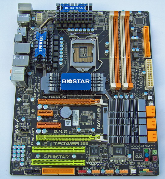
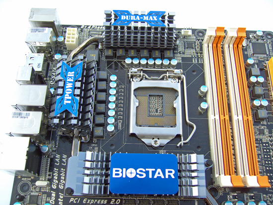
The heatsinks bearing the TPower and DURA-MAX logos provide cooling for the 8-phase uPI CPU PWM circuit, with an additional 4 phase supply for VTT (the integrated memory controller). The IR FET’s are specified at around 30 amps each, which should allow for ample overclocking headroom. The two CPU PWM heatsinks are connected by a heatpipe which also links to the BIOSTAR logo heatsink you see in the bottom of the picture. This pipe extends further to the PCH heatsink, allowing the entire assembly to be cooled with a single fan. All heatsinks are fastened with push-pins rather than screw fittings, although we found contact pressure was sufficient in this instance.
Despite the bulk used in these heatsinks, were going to recommend users to apply active cooling across the central heatsink when overclocking, especially if ramping PWM switching frequencies for heavy load testing. On the subject of heavy loads; BIOSTAR is using revised FOXCONN sockets on their boards. We’ve had no socket related problems during the course of this review and have not heard of any user reports thus far using BIOSTAR boards.
We’re a little surprised to find that there are only three onboard fan headers, one of which is assigned to the CPU. This leaves two (actually one) additional headers for active board cooling should high temperatures become a hindrance to overclocking. Do note; the SYS_FAN 2 header at the right side of the board will not be accessible if you plug a long GPU into the primary PEG slot. We’d like to have seen BIOSTAR put a little more time and consideration with regards to the number of headers and their placement on this motherboard given the target audience.
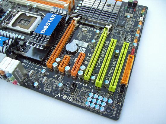
Expansion slot layout from the top down is comprised of, PCI/e x16 (x8 if the second x16 slot is filled), PCI/e x1, PCI/e x4, PCI/e x8 and two PCI slots at the bottom. You lose access to the PCI/ex 1 slot as soon as you put a GPU with a dual slot cooler in the first PEG slot, although you can use the PCI/e x4 slot instead. Running dual GPU’s will also limit users to one PCI slot, although we don’t see that as a huge deal breaker these days.
While we’re on the subject of expansion slots, we found the PCI/e retention latches to be a pain when trying to remove our 4870X2 GPU from the board. The lever does not protrude far enough to allow access easily, especially if the board is placed in a case. We had to use a set of long-nose pliers to grab the latch and force it downwards so that we could remove the GPU from the slot.
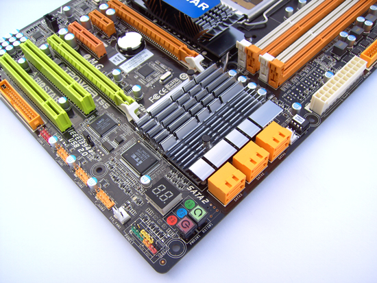
Six right angle SATA ports are available via the Intel P55 PCH. A LED hex post code reader and power/reset switches are located in the lower right corner for open test bed users. A single DIL socket BIOS chip is located above the SATA ports, while the associated CMOS clear jumper is located to the right of the last PCI slot. CMOS clear access is certainly going to be hampered somewhat if the last PCI slot is occupied, but we never needed it. Unfortunately there is no rear I/O panel CMOS clear switch, which will leave users pulling side panels off cases should the board fail to post after changing BIOS settings.
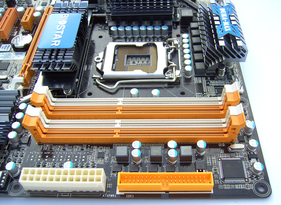
ATX 12V and IDE connectors are placed along the right edge of the board. A full spread of voltage reading pads are provided, and located between the ATX 12V connecter and the last DIMM slot. DIMM voltage is supplied by a 2-phase PWM circuit, which is pretty much the norm for boards in this price range and should certainly be more than adequate for the platform.
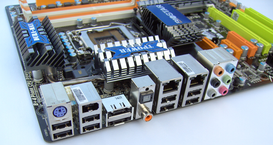
Rear I/O options include: 1 PS/2, 8 USB, 2 E-SATA, 1 IEEE-1394a, 2 RJ45 LAN, 1 S/PDIF & 1 Optical out and finally 6 AUDIO out jacks (Realtek ALC888).
Originally published at https://www.anandtech.com/show/2880 (Wayback Machine).