
Killing the Business Desktop PC Softly
- Posted in
- IT Computing
Consolidated Client Infrastructure (CCI)
The blade chassis in which these blade PCs find a home is pretty simple. It consists of two redundant power supplies, a few redundant fans, and a BladeSystem switch.
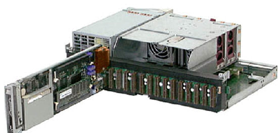
Inside the PC blade chassis
The HP BladeSystem PC blade switch - which is the thin "drawer" beneath the fan module - is a Layer 2 switch that links up the 20 blade PCs (100 Mbit) to 4 Gbit Ethernet uplink ports. The goal is to have 2 ports of 1 Gbit/s uplink and a full failover to the other ports. You can also use the 4 fiber-optic Ethernet SFP slots if you buy the optional HP SX SFP Transceivers. Unfortunately using fiber optic networking also means that the copper Ethernet ports are disabled.
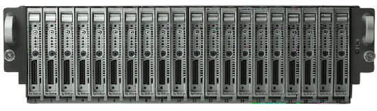
The blade switch is quite a capable switch supporting up to 256 virtual LANs, Spanning Tree Protocols, link aggregation, QoS, and trunking.
So now that we know what components are used, how does this all work? You could simply assign one thin PC to one blade PC, the static CCI model. But since moving over to CCI is all about lowering TCO, there is a better way to do it. A user logs into any thin client. The thin client connects and authenticates to an Active Directory server which works together with the Session Allocation Manager (SAM). SAM determines based on its database whether the user has a desktop session running or not. If so, SAM reconnects the user to the same session. If not, SAM establishes a session and connects the thin client to the appropriate blade PC and tells the blade PC where it can find the user documents, which are stored on the central storage server (NAS or SAN).
HP calls this the dynamic model of CCI. To make this work you need the following:
The blade chassis in which these blade PCs find a home is pretty simple. It consists of two redundant power supplies, a few redundant fans, and a BladeSystem switch.
Inside the PC blade chassis
The HP BladeSystem PC blade switch - which is the thin "drawer" beneath the fan module - is a Layer 2 switch that links up the 20 blade PCs (100 Mbit) to 4 Gbit Ethernet uplink ports. The goal is to have 2 ports of 1 Gbit/s uplink and a full failover to the other ports. You can also use the 4 fiber-optic Ethernet SFP slots if you buy the optional HP SX SFP Transceivers. Unfortunately using fiber optic networking also means that the copper Ethernet ports are disabled.
The blade switch is quite a capable switch supporting up to 256 virtual LANs, Spanning Tree Protocols, link aggregation, QoS, and trunking.
So now that we know what components are used, how does this all work? You could simply assign one thin PC to one blade PC, the static CCI model. But since moving over to CCI is all about lowering TCO, there is a better way to do it. A user logs into any thin client. The thin client connects and authenticates to an Active Directory server which works together with the Session Allocation Manager (SAM). SAM determines based on its database whether the user has a desktop session running or not. If so, SAM reconnects the user to the same session. If not, SAM establishes a session and connects the thin client to the appropriate blade PC and tells the blade PC where it can find the user documents, which are stored on the central storage server (NAS or SAN).
HP calls this the dynamic model of CCI. To make this work you need the following:
- As many thin PCs as users connected to an Ethernet LAN
- As many blade PCs as the maximum amount of concurrent users plus (at least) one (for fail over purposes) connected via the PC blade switch on the same Ethernet LAN
- One SAM and Active Directory server connected to the same LAN
- A Central storage server connected via FC, iSCSI (SAN) or LAN (NAS) to the SAM server
Originally published at https://www.anandtech.com/show/2279 (Wayback Machine).