
Enermax Revolution 85+ High Efficiency PSU
- Posted in
- Cases/Cooling/PSUs
Internals
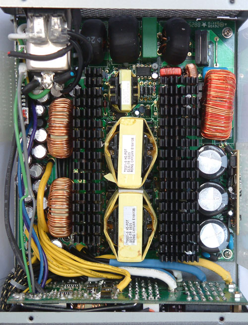
So far things have been pretty typical for a power supply review. After all, there are only so many ways to design a standard PSU chassis and provide cable harnesses. Now we come to the interesting part: the internals. Enermax did a tremendous job designing this power supply, but let's start at the beginning.
When I first saw the filtering stage, I asked the representatives at Enermax if CWT is the ODM. They responded by threatening to beat me up. ;-) Anyway, the filtering stage looks very good and has all of the necessary components. The coil sits on top of the PCB, covered with shrinking hose -- hence the similarity to CWT PSUs. Right nearby are the rectifier bridges, both without heatsinks. The PFC stage follows next and the coil is placed on a solid socket. Matsushita builds the three primary capacitors, rated for 220µF and 400V at 85°C.
Enermax is particularly proud of their transformers, since they synchronized both of them for quad forward circuitry. Two synchronized transformers will share the work equally, which makes the work more efficient. The power supply also features eight safety features such as OCP (Over Current Protection), UVP (Under Voltage Protection) for the AC part, UVP (Under Voltage Protection) for the DC part, OPP (Over Power Protection), OTP (Over Temperature Protection), SIP (Surge & Inrush Protection), and SCP (Short Circuit Protection).


This power supply uses a DC-to-DC topology, which means that the 3.3V and 5V rails do not come directly from the transformer anymore. The transformers can now be built for the sole purpose of delivering a stable 12V output. In DC-to-DC designs, so far the extra circuitry has been included on the main PCB in the secondary stage of the PSU. Enermax relocated this functionality to a sister PCB that we will describe in the next paragraph. The secondary stage in this power supply now only has to deal with the six 12V rails. The capacitors for this purpose are all made by Chemi-Con, one of the best but still affordable Japanese capacitor manufacturers.
So where are the 3.3V and 5V rails created? Let's have a look at the large sister PCB where the cable management sockets are located. The left side is where it happens. The upper part is for the 5V output and the bottom is for 3.3V. The output feeds directly into the cable harnesses, and from there on to the peripherals. Since this is done totally independent from the other 12V rails, this power supply can output 99% of its rated power on just the 12V rails, which we will verify in a moment. Other power supplies that generate the 5V and 3.3V rails from the transformer normally have problems with the voltage distribution if not loaded according to ATX-norm.
Originally published at https://www.anandtech.com/show/2662 (Wayback Machine).