
Xigmatek NRP-HC1001 and NRP-HC1201 Power Supplies
- Posted in
- Cases/Cooling/PSUs
Internals
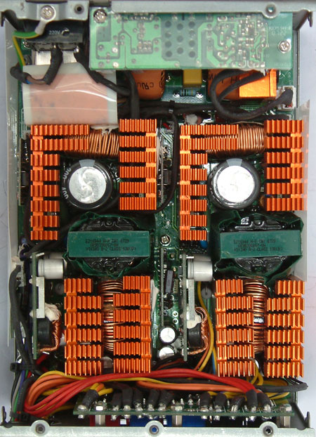
Opening this unit reveals an inside layout we haven’t seen before. There are actually two power supplies in this one unit so to speak. To make it a little clearer we marked the different parts of the power supply.
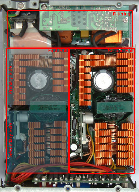
On the top we have the well built filtering stage. It’s easy to recognize CWT power supplies by their filtering stage, which is well equipped as always. This unit then splits into two different primary sides as shown above. Both primaries are fully equipped as is standard in modern switching power supplies. Both sides have their own transformers which are easily recognizable through their green covering.
Following that we come to the secondary parts for both sides. There are solid capacitors installed on a smaller sister PCB because the space on the PCB was just not enough, though there are still some normal electrolyte capacitors close to the cable management PCB. What happens here in fact is that one half of the PSU provides the 12V1 and 12V4 and the 3.3V rail and the other half distributes 12V2 and 12V3 together with the 5V rail. That’s why the diagram shows such unusual characteristics.


The filtering stage was separated in two due to the lack of space. There are caps on the small PCB upside down and caps and coils on the main PCB. Each side has a main capacitor made by Hitachi and rated at 390µF and 400V. The secondary side features all solid caps on a small sister PCB vertically positioned relative to the main PCB. There are also smaller electrolyte capacitors behind the heatsinks as well. The backside shows the PCB for the cable management. There are clear markings with the different rails on the top of the PCB.
Originally published at https://www.anandtech.com/show/2501 (Wayback Machine).