
Foxconn MARS: God of War Performance?
- Posted in
- Motherboards
Foxconn MARS: Board Layout and Features
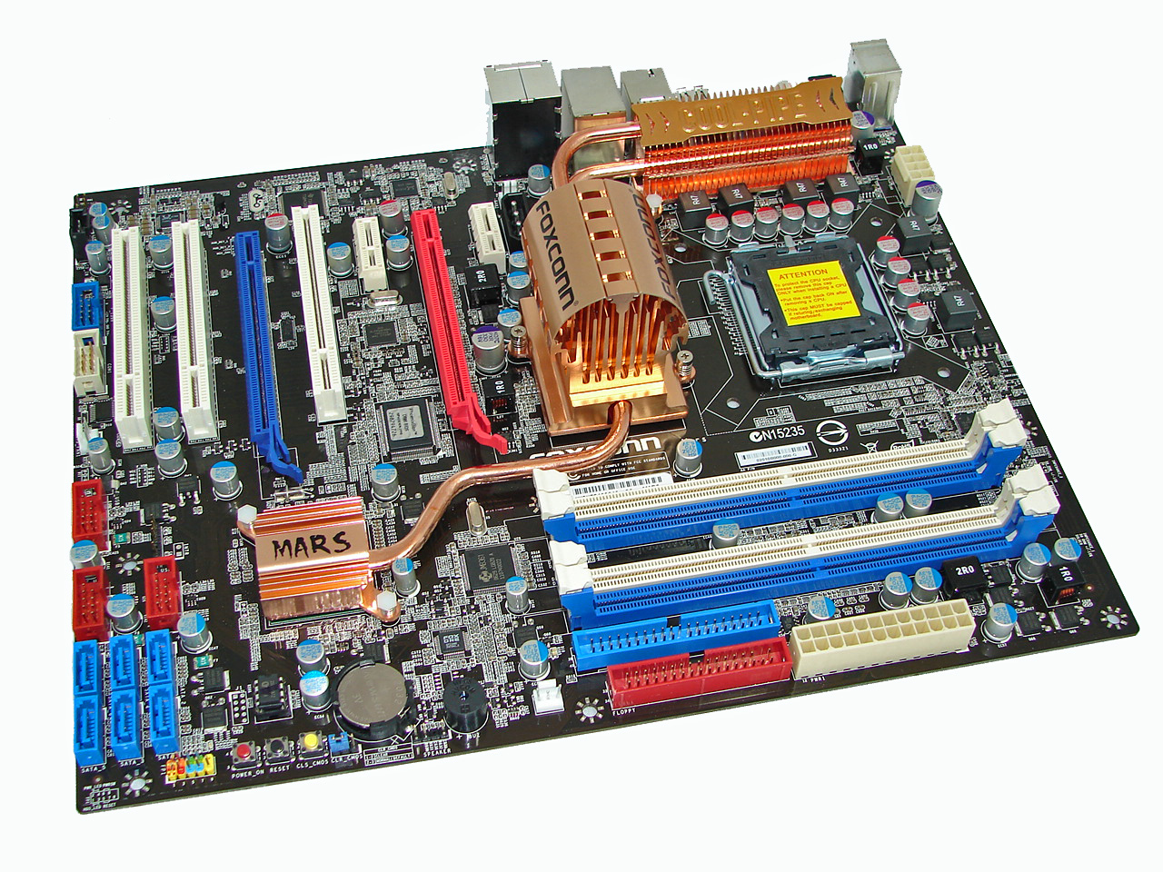
We have to admit that Foxconn spent some time on the layout of this board, although the color scheme is more reminiscent of an American July Fourth celebration than the dark black and blood red colors on the box and documentation materials. In fact, other than the Foxconn name, the black board and cooling arrangement almost seems more like an ASUS product, which certainly isn't a bad thing if they can provide that level of performance. The board was a snap to install in our Antec P180 and Cooler Master 830 cases with most connections easily reached. The board features a six-phase voltage regulator system and six-layer PCB and provided excellent stability throughout testing. The Foxconn MARS features 100% use of Conductive Polymer Aluminum Solid Capacitors.
The board comes with a total of five fan headers (1 x 4-pin, 4 x 3-pin) that provided a nice balance of cooling options. The CPU, Northbridge, and System fans can be individually controlled via the BIOS and the Foxconn Aegis program within Windows. Each header type has the option of Full Speed, Duty-Cycle, and Smart Fan settings within the BIOS. The System Header setting controls the three system fans as a group and not individually. Foxconn also provides a snap-on fan for the Northbridge heatsink that provides additional cooling, and the fan is almost whisper quiet. However, this fan cannot control temperatures properly when the Northbridge voltage was set over 1.7V, so additional cooling will be required if you are heavily overclocking the system.
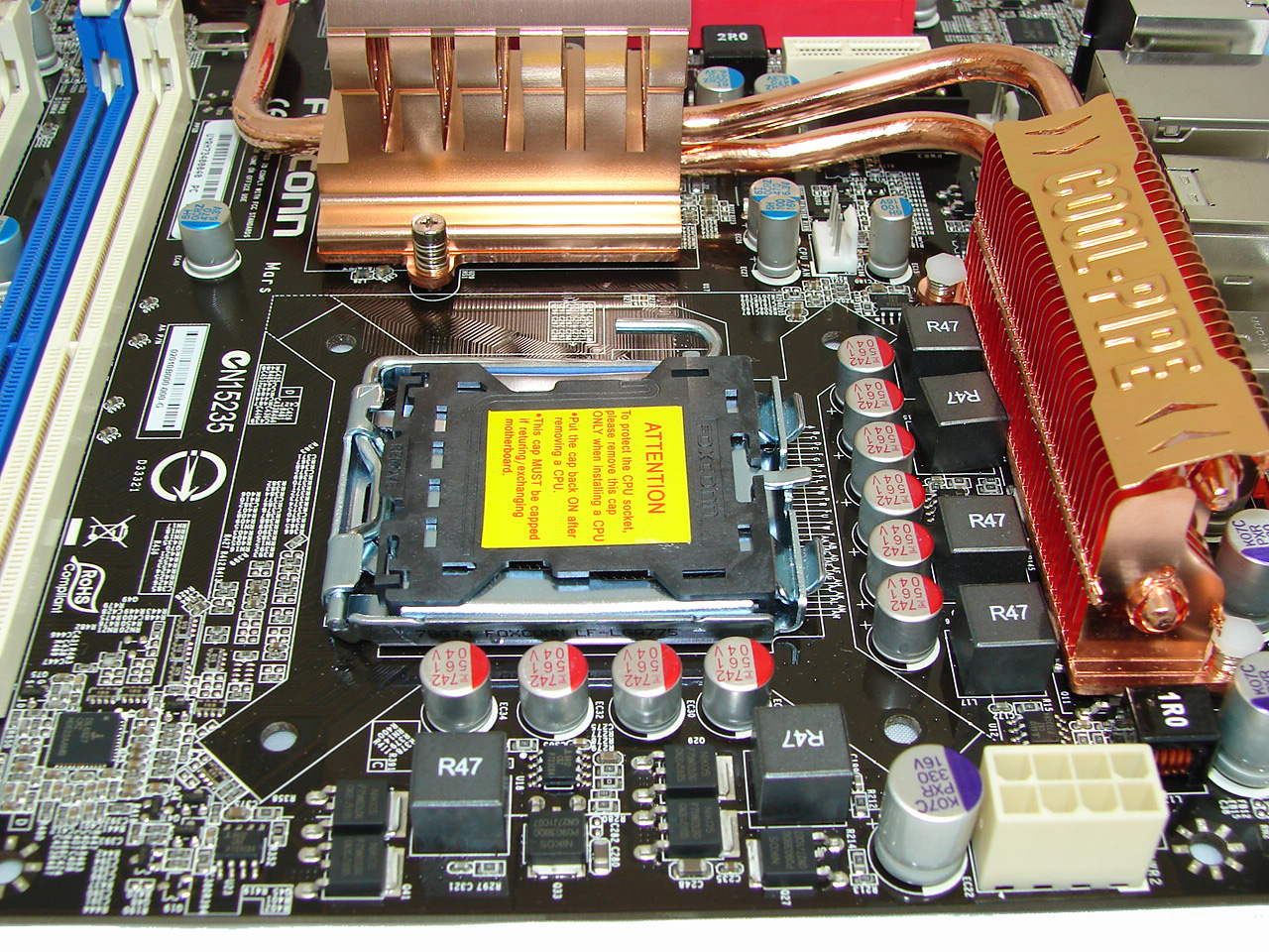
Around the CPU socket area, we find an ample amount of room for the majority of cooling solutions. We utilize the stock heatsink/fan in our base testing but also install several aftermarket Socket-775 cooling solutions such as the Tuniq 120 and Thermalright Ultra 120 eXtreme during our overclocking tests. However, based upon our initial overclocking tests, if a vertical mounted fan in an air cooling unit such as the Tuniq 120 or water-cooling is utilized then additional air cooling will be required on the MCH and PWM areas. In other words, the cooling seems to be designed with the use of a downward blowing CPU HSF fan in mind.
The 8-pin ATX power connector is located on the edge of the board behind the PS/2 keyboard port and did not interfere with our various cooling units. The Cool-Pipe heat system can easily be removed if you wish to water cool the MCH/ICH chipsets. The only problem during testing is that the Cool-Pipe logo plate adhesive failed and allowed the right section of the plate to slowly bend upwards. Foxconn confirmed they will be using a different adhesive for the production boards.
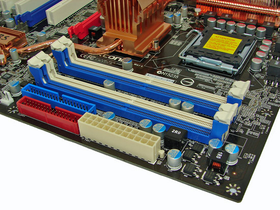
The DIMM module slots' color coordination is correct for dual channel setup based upon the premise of installing DIMMs in the same colored slots for dual-channel operation. Installing memory modules will be not be a problem with a full size video card placed in the first PCI Express x16 slot.
The 24-pin ATX power connector is located on the edge of the board along with the floppy drive and IDE connectors. The first system fan header is located to the left of the floppy connector. We suggest installing the IDE cable before the memory and floppy drive cable if you plan on a four DIMM memory configuration.
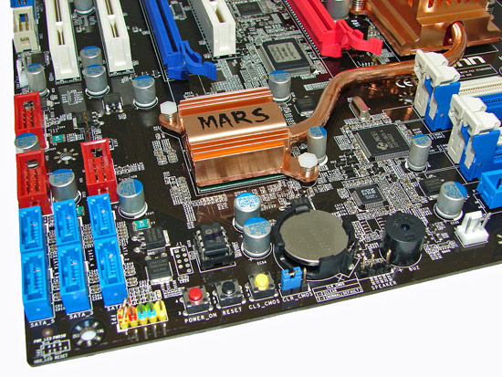
We found the positioning of the six blue ICH9R SATA ports to be excellent when utilizing the expansion slots, as they are out of the way of most longer cards (i.e. graphics cards). The ICH9R chipset is passively cooled and remained fairly cool to the touch throughout testing, although temperatures did increase with a CrossFire setup. Right above the SATA ports are three red connectors for the additional USB ports and the second system fan header.
In a nod to those users who run their systems on an open platform or get tired of hooking up the chassis panel connections, Foxconn has added power on, reset, and clear CMOS buttons on the board. These buttons have always been useful for us and should be standard on any board in this market segment. Of course a POST Code Debug LED would have been nice but we won't complain... well, not too loudly anyway.
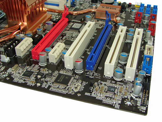
The board comes with two physical PCI Express x16 connectors (1 x16, 1 x4 electrical), two PCI Express x1 connectors, and three PCI 2.2 connectors. The second PCI Express x1 and PCI slots will be blocked by a dual slot graphics card. Several cards we tried in the first PCI Express x1 slot also had a tight fit with a dual slot graphics card installed. When utilizing CrossFire on this board, the two PCI Express x1 slots will be disabled by the BIOS. However, we highly recommend using a 975X or the upcoming X38 chipset for CrossFire as our upcoming comparison article will show. A 4-pin 12V Molex connector is to the left of the first PCI Express x1 slot and should be used for CrossFire operation.
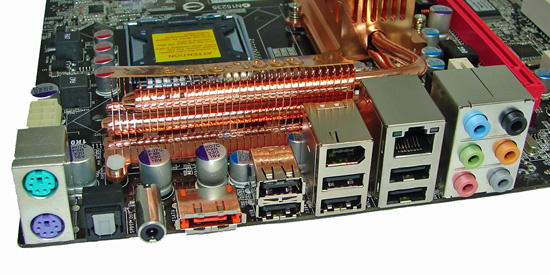
The rear panel contains the standard PS/2 mouse and keyboard ports. The panel also includes an RJ-45 LAN port with activity indicator lights, six USB ports, and optical/coaxial out S/PDIF ports. The audio panel consists of six ports that can be configured for 2, 4, 6, and 8-channel audio connections for the Realtek ALC888 HD codec. Finally, there is an eSATA port along with an IEEE 1394 port, providing a wide array of connection options on the rear panel.
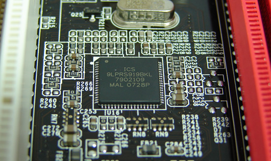
Foxconn utilizes the ICS 9LPRS919BKL clock control chipset on this board and the latest version of SetFSB works with it.
 |
| Click to enlarge |
We have to admit that Foxconn spent some time on the layout of this board, although the color scheme is more reminiscent of an American July Fourth celebration than the dark black and blood red colors on the box and documentation materials. In fact, other than the Foxconn name, the black board and cooling arrangement almost seems more like an ASUS product, which certainly isn't a bad thing if they can provide that level of performance. The board was a snap to install in our Antec P180 and Cooler Master 830 cases with most connections easily reached. The board features a six-phase voltage regulator system and six-layer PCB and provided excellent stability throughout testing. The Foxconn MARS features 100% use of Conductive Polymer Aluminum Solid Capacitors.
The board comes with a total of five fan headers (1 x 4-pin, 4 x 3-pin) that provided a nice balance of cooling options. The CPU, Northbridge, and System fans can be individually controlled via the BIOS and the Foxconn Aegis program within Windows. Each header type has the option of Full Speed, Duty-Cycle, and Smart Fan settings within the BIOS. The System Header setting controls the three system fans as a group and not individually. Foxconn also provides a snap-on fan for the Northbridge heatsink that provides additional cooling, and the fan is almost whisper quiet. However, this fan cannot control temperatures properly when the Northbridge voltage was set over 1.7V, so additional cooling will be required if you are heavily overclocking the system.
 |
| Click to enlarge |
Around the CPU socket area, we find an ample amount of room for the majority of cooling solutions. We utilize the stock heatsink/fan in our base testing but also install several aftermarket Socket-775 cooling solutions such as the Tuniq 120 and Thermalright Ultra 120 eXtreme during our overclocking tests. However, based upon our initial overclocking tests, if a vertical mounted fan in an air cooling unit such as the Tuniq 120 or water-cooling is utilized then additional air cooling will be required on the MCH and PWM areas. In other words, the cooling seems to be designed with the use of a downward blowing CPU HSF fan in mind.
The 8-pin ATX power connector is located on the edge of the board behind the PS/2 keyboard port and did not interfere with our various cooling units. The Cool-Pipe heat system can easily be removed if you wish to water cool the MCH/ICH chipsets. The only problem during testing is that the Cool-Pipe logo plate adhesive failed and allowed the right section of the plate to slowly bend upwards. Foxconn confirmed they will be using a different adhesive for the production boards.
The DIMM module slots' color coordination is correct for dual channel setup based upon the premise of installing DIMMs in the same colored slots for dual-channel operation. Installing memory modules will be not be a problem with a full size video card placed in the first PCI Express x16 slot.
The 24-pin ATX power connector is located on the edge of the board along with the floppy drive and IDE connectors. The first system fan header is located to the left of the floppy connector. We suggest installing the IDE cable before the memory and floppy drive cable if you plan on a four DIMM memory configuration.
We found the positioning of the six blue ICH9R SATA ports to be excellent when utilizing the expansion slots, as they are out of the way of most longer cards (i.e. graphics cards). The ICH9R chipset is passively cooled and remained fairly cool to the touch throughout testing, although temperatures did increase with a CrossFire setup. Right above the SATA ports are three red connectors for the additional USB ports and the second system fan header.
In a nod to those users who run their systems on an open platform or get tired of hooking up the chassis panel connections, Foxconn has added power on, reset, and clear CMOS buttons on the board. These buttons have always been useful for us and should be standard on any board in this market segment. Of course a POST Code Debug LED would have been nice but we won't complain... well, not too loudly anyway.
The board comes with two physical PCI Express x16 connectors (1 x16, 1 x4 electrical), two PCI Express x1 connectors, and three PCI 2.2 connectors. The second PCI Express x1 and PCI slots will be blocked by a dual slot graphics card. Several cards we tried in the first PCI Express x1 slot also had a tight fit with a dual slot graphics card installed. When utilizing CrossFire on this board, the two PCI Express x1 slots will be disabled by the BIOS. However, we highly recommend using a 975X or the upcoming X38 chipset for CrossFire as our upcoming comparison article will show. A 4-pin 12V Molex connector is to the left of the first PCI Express x1 slot and should be used for CrossFire operation.
The rear panel contains the standard PS/2 mouse and keyboard ports. The panel also includes an RJ-45 LAN port with activity indicator lights, six USB ports, and optical/coaxial out S/PDIF ports. The audio panel consists of six ports that can be configured for 2, 4, 6, and 8-channel audio connections for the Realtek ALC888 HD codec. Finally, there is an eSATA port along with an IEEE 1394 port, providing a wide array of connection options on the rear panel.
Foxconn utilizes the ICS 9LPRS919BKL clock control chipset on this board and the latest version of SetFSB works with it.
Originally published at https://www.anandtech.com/show/2337 (Wayback Machine).