
Image Quality Analysis Fall 2003: A Glance Through the Looking Glass
- Posted in
- GPUs
Texture Mapping and Filtering
In the beginning was the wire frame, and it was good. But texture mapping changed completely the face of computer generated 3D graphics. Everything from coloring, to lighting and shadows, to bumping and displacement can be done with texture mapping. For this discussion, we will be talking about mipmapping, bilinear, trilinear, and anisotropic filtering.To set the stage, our 3D scene has an object and a texture map (an image to be applied to the object). When we stare “through the looking glass,” we see that each screen pixel maps to a particular area of our object. Likewise, each area on the object maps to an area in the texture map. Unfortunately, a texture map has a fixed number of data points (pixels in the image), while the surface of the object is continuous. This means that it is possible for an area on the object to map to a position that lies between pixels in the texture image. In order to fill in the gaps, developers need to choose a method to interpolate existing data. The first method developers used to solve this problem was simply to make the color of an area equal to that of the nearest pixel in the texture map.
The image quality resulting from using the nearest texel (a pixel in a texture map) is something commonly referred to as pixelization (large blocks of color visible when objects with low resolution textures fill the screen). Anyone who's played early first-person shooters (like Doom, Duke3D, etc.) will know this from how the screen looks when pressed up against a wall.
To solve this, rather than using the nearest texel in the texture map, we can do linear interpolation. We take the 4 surrounding texels, and interpolate between the two pairs of pixels in one direction. With the two resulting points, we then do another linear interpolation to get something closer to what the color should be. This is called bilinear filtering.
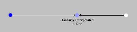 |
| The light blue color is interpolated linearly from the other two. |
Another problem with what we have already talked about is that when high resolution textures are used on a surface that is far away, one screen pixel can be mapped to an area in the texture map, while the neighboring screen pixels are mapped to entirely different areas of the texture. Essentially, the size of the screen pixel is much greater than that of the texel. The visual result of this is a shimmering or sparkling in distant textures.
We can fix this by making multiple versions of texture maps with different resolutions. These multiple resolution texture maps are mipmaps (as this is a description of mipmapping). A Level of Detail (LOD) calculation based on the distance of the area on the object that we are texturing to the viewer is used to choose a mipmap level with texels close to the size of (but not smaller than) screen pixels.
One of the things that is completely different between ATI and NVIDIA is the way LOD is calculated for mipmapped textures. NVIDIA uses the Euclidean distance (sqrt(x2, y2, x2)) in their calculations, while ATI uses a weighted Manhattan distance calculation (.28*x+.53*y+.19*z). This causes the way textures look to vary a great deal between GPUs when looking at anything but very near or very far surface.
Of course, we still have problems that we need to solve. When the LOD calculation dictates a change in the mipmap being used on a surface, we can see a discontinuity in the texturing of that surface. To combat this, trilinear filtering was devised. First, we do filtering on the two surrounding mipmap levels, then interpolate between the resulting values.
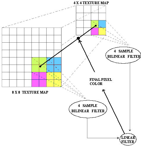 |
| This diagram shows one way to do trilinear filtering. |
The result is a smooth transition between mipmap levels. Of course, there are plenty of different algorithms for doing all this interpolation, and there is not a GPU on the market that does full trilinear filtering all the time. This operation is very expensive to do for every pixel on the screen. There are plenty of optimizations to make trilinear faster, such as only doing bilinear filtering where banding isn't an issue. This is acceptable as long as there is no perceptible loss in visual quality.
But the madness doesn't stop there. As it happens, trilinear filtering is isotropic. What this means to us is that trilinear filtering produces blurry images when not viewed straight on. The reason this happens is that the pixels in the mipmap levels are laid out in a square grid. Anisotropic filtering allows us to change the shape of the region we sample and interpolate between each mipmap based on the viewing angle. (Think of this as needing to be done for the same reason tilting a square object makes the far edge look narrower than the near edge.) The way this is done is also up to the implementation, thus adding another level of complexity in determining the color of one pixel due to one texture on one surface.
Originally published at https://www.anandtech.com/show/1205 (Wayback Machine).