
Silverstone Zeus 1200W: Designed for the Power Hungry
- Posted in
- Cases/Cooling/PSUs
The Inside
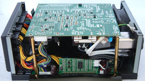
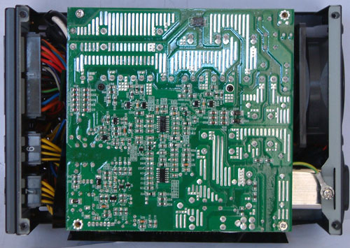
The housing is easy to open and with the top plate removed we can see the back of a PCB. Now it's clear why Silverstone needed to stick to an 80mm fan because the sandwiched PCB design doesn't allow the use of a larger fan. Sandwiched PCBs (i.e. two PCBs with all the components on the inside) are becoming a more and more common design these days; the Antec Signature Series we just tested also used this approach. In general, one can say that the designers leave the filtering stage and the primary stage with mostly AC-voltage on one PCB and the second one carries the secondary stage with DC voltage only. Due to a lack of space, the standby rail also usually resides on the first PCB.
Let's return to a problem we mentioned earlier regarding multiple vs. single 12V rails. After a user has scratched away the white sticker on the side of the power supply he will recognize that his warranty is gone and it didn't even help further since the manufacturer placed a plastic sheet behind the sticker, making it impossible to reach the little switch. You need to open the power supply to use this switch, which is quite unfortunate. During testing we had several problems with the 17A on the 12V rails, which led us to the point that we combined all of the 12V rails into one and our load problem was gone. The problem is that Silverstone doesn't mark the 12V wires on each harness to differentiate the 12V rails, so the user/reviewer is unable to see immediately which 12V rail is being connected to the what components (or in our case, the programmable load). Most end-users will not need to worry about this problem, as 17A per 12V rail should be sufficient. You may need to juggle a few connections if you somehow manage to create a 1000W or higher load, but the multiple PEG connections already address that to a large degree.
First PCB
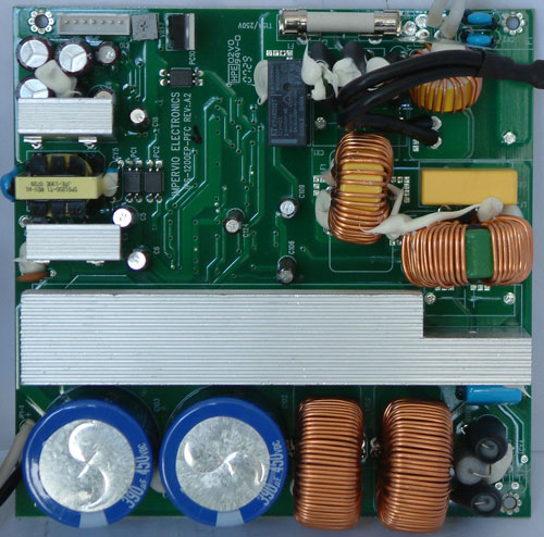
The first PCB in this PSU carries the filtering stage, the primary stage, and the standby circuit. The filtering stage is easy recognizable through its fuse on the top, several caps, and coils. The rectifier bridge is hiding under the heatsink on the right side. There are two large coils and two main-caps, as the designers couldn't place one single large cap due to the reduced possible height. The two caps are identical and come from Hitachi, both rated at 390µF and 450V, which is well within feasibility. The upper left side features the standby circuit with its own small transformer. Besides the circuitry we see the name Impervio printed on the PCB, which is a familiar name with Silverstone power supplies. Even though this power supply still seems to be produced by IS Quasar; the designer is Impervio in cooperation with Silverstone.
Secondary PCB
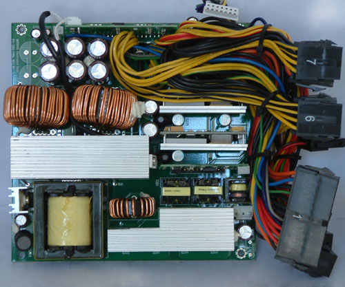
The second PCB is much more packed than the first one, carrying more components. First, we have the transformer that is responsible for the 12V rail. Then we see a couple of heatsinks, smaller transformers, coils, and Nippon Chemi-Con caps in the top. We also see another feature not many power supplies have used until now. The 3.3 and 5V rail are generated by VRMs, which can be found on the middle right side of the PCB. This may cause you to think the time has come where we won't need any of the additional rails anymore. Since modern motherboards also use VRMs to convert the voltage into whatever is needed by the components, it seems like a good time to switch to 12VDC only. A few problems remain with peripheral components like SATA drives or optical drives that still sometimes use a voltage other than 12V, but these don't need much of the other voltages.


Originally published at https://www.anandtech.com/show/2561 (Wayback Machine).