
Corsair HX1000W
- Posted in
- Cases/Cooling/PSUs
Internals
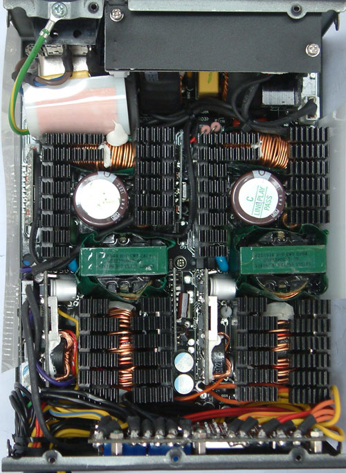
Opening this unit shows almost exactly the same interior as we have seen previously with Xigmatek or Thermaltake. Corsair changed a few things that are not necessarily easily visible. Let's first start with checking the layout. As we mentioned in the Xigmatek review, this power supply is in fact split into two halves. Each half acts as a completely independent power supply with 12V and a smaller voltage rail. The 5Vsb rail is generated within its own circuitry, which is located above the filtering stage on its own PCB. We have the filtering stage at the top with coils and capacitors and then we have a big rectifier bridge that has its own little heatsink in the top right corner of the picture. From there, the power supply splits in half and each side has its own primary stage containing amongst other things the PFC stage with some nice Japanese capacitors from Nippon Chemi-Con. Both are rated at 420V and 330µF at 105°C.


Each side has only one transformer where the 12V rail is generated. Each of the sides has a smaller rail of 3.3V or 5V split from each of the 12V rails. The difference from other similar units lies in the secondary stage. Competitors only have a few solid-state capacitors here, which are supposed to have a much longer life expectancy. Corsair has the complete secondary stage equipped with solid-state capacitors even for the smaller voltage rails. There are only two normal electrolyte capacitors hidden under the cables. The heatsinks are very small due to the lack of space, but they have a decent surface area through the use of many small fins. The inside looks very packed and there are some areas where the airflow will be restricted, but most of the parts will be cooled just fine.
Originally published at https://www.anandtech.com/show/2513 (Wayback Machine).