
nForce4 SLI Motherboards: Premium Performance at a Bargain Price
- Posted in
- Motherboards
ASUS A8N-SLI Premium: Features
Asus has engineered a very effective cooling system that utilizes a small heat sink attached to a heat pipe that comes in direct contact with the nForce4-SLI chipset. This system then transfers the heat to a finned heat sink that also cools the MOSFETs. The whole system is fanless, but relies on the exhaust air generated by the CPU heat sink fan to cool the finned heat sink. We would recommend that a fan be placed on or near this heat sink when water or phase change cooling systems are utilized.
The Silicon Image 3114R SATA II RAID (red) ports are located to the left of the CK8-04 chipset and above the nForce4 SATA II ports. The SATA II ports feature the old attachment design that could create connection issues.
The nForce4 USB connectors, IEEE1394a connector, Com1 serial port, and System Panel connector are located along the left edge of the board. The CMOS reset is a traditional jumper design located between the battery and Super I/O chipset that proved to be inconvenient at times.
However, in between the two x16 PCI Express slots are the two PCI-E slots. This configuration could potentially render the PCI-E x1 slot useless when utilizing the first x16 PCI Express slot. The amount of space in-between the two PCI-E x16 slots is excellent and allows for a two-slot or third party video card cooling solution to be utilized. The first PCI slot next to the second PCI-E x16 slot will be rendered useless when utilizing a two-slot video card cooling solution.
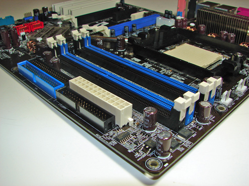
The finned heat sink, which cools the MOSFETs and is part of the heat pipe system, is visible along with the 4-pin 12V molex connector next to the PCI-E x16 slot. The molex connector is required when utilizing two video cards in SLI operation.
Asus places the four-pin 12V auxiliary power connector at the top of the CPU socket area, but out of the way of most aftermarket cooling solutions.
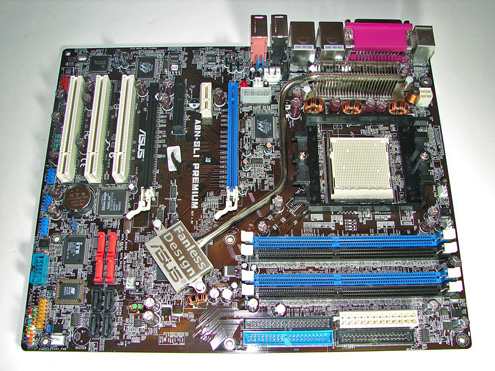
Asus has engineered a very effective cooling system that utilizes a small heat sink attached to a heat pipe that comes in direct contact with the nForce4-SLI chipset. This system then transfers the heat to a finned heat sink that also cools the MOSFETs. The whole system is fanless, but relies on the exhaust air generated by the CPU heat sink fan to cool the finned heat sink. We would recommend that a fan be placed on or near this heat sink when water or phase change cooling systems are utilized.
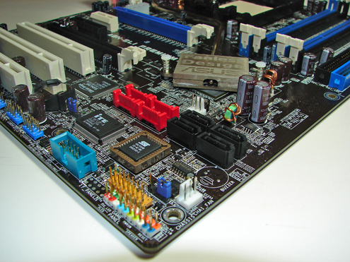
The Silicon Image 3114R SATA II RAID (red) ports are located to the left of the CK8-04 chipset and above the nForce4 SATA II ports. The SATA II ports feature the old attachment design that could create connection issues.
The nForce4 USB connectors, IEEE1394a connector, Com1 serial port, and System Panel connector are located along the left edge of the board. The CMOS reset is a traditional jumper design located between the battery and Super I/O chipset that proved to be inconvenient at times.
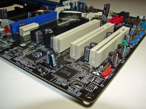
However, in between the two x16 PCI Express slots are the two PCI-E slots. This configuration could potentially render the PCI-E x1 slot useless when utilizing the first x16 PCI Express slot. The amount of space in-between the two PCI-E x16 slots is excellent and allows for a two-slot or third party video card cooling solution to be utilized. The first PCI slot next to the second PCI-E x16 slot will be rendered useless when utilizing a two-slot video card cooling solution.
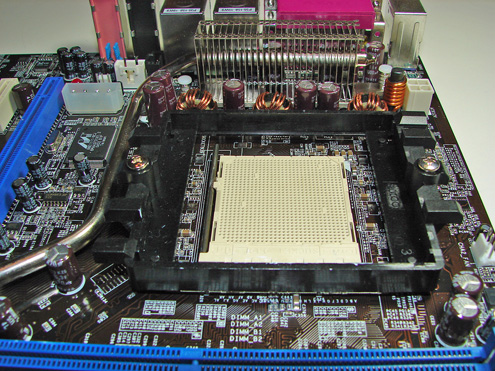
The finned heat sink, which cools the MOSFETs and is part of the heat pipe system, is visible along with the 4-pin 12V molex connector next to the PCI-E x16 slot. The molex connector is required when utilizing two video cards in SLI operation.
Asus places the four-pin 12V auxiliary power connector at the top of the CPU socket area, but out of the way of most aftermarket cooling solutions.
Originally published at https://www.anandtech.com/show/1913 (Wayback Machine).