
FIRST LOOK: ULi M1695 PCIe/AGP Socket 939 for Athlon 64
- Posted in
- Motherboards
Basic Features: ULi AP9507A (M1695/M1567)
| ULi AP9507A (M1695/M1567) | |
| CPU Interface | Socket 939 Athlon 64 |
| Chipset | ULi M1695 Northbridge - ULi M1567 Southbridge |
| BUS Speeds | 200MHz to 400MHz in 1MHz Increments |
| PCIe Speeds | 75-125MHz in 1MHz Increments |
| PCI/AGP | Fixed at 33/66 |
| Core Voltage | Startup, 0.825V to 1.55V in 0.025V increments |
| CPU Clock Multiplier | Startup, 4x-25x in 1X increments |
| HyperTransport Frequency | 1000MHz (1GHz) |
| HyperTransport Multiplier | 200, 400, 600, 800, 1000 |
| DRAM Voltage | NO Adjustments |
| HyperTransport Voltage | NO Adjustments |
| Memory Slots | Four 184-pin DDR DIMM Slots Dual-Channel Configuration Regular Unbuffered Memory to 4GB Total |
| Expansion Slots | 1 PCIe x16 (or 2 PCIe x8) 1 AGP 8X 2 PCIe x1 2 PCI Slots |
| Onboard SATA/RAID | 2 SATA Drives by ULi M1567 (RAID 0, 1, JBOD) |
| Onboard IDE/IDE RAID | Two Standard ATA133/100/66 (4 drives) |
| Onboard USB 2.0/IEEE-1394 | 8 USB 2.0 ports supported by ULi M1567 No Firewire (Optional) |
| Onboard LAN | 10/100 Ethernet by Realtek PNY (Gigabit LAN Optional) |
| Onboard Audio | AC '97 2.3 6-Channel by Realtek ALC655 |
| BIOS Revision | Award OC50624A (6/24/2005) |
The ULi Award BIOS provides a wide range of BIOS control options, particularly considering that this is a Reference Board used to qualify a chipset. The wide 200 to 400 range for CPU clock was a pleasant surprise, but it is somewhat academic with no memory voltage controls present in the BIOS.
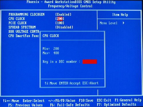
The included vCore adjustments and PCIe speed adjustments were also a nice addition, although the range to just 1.55V is very limited for Clawhammer processors, which are 1.50V at default.
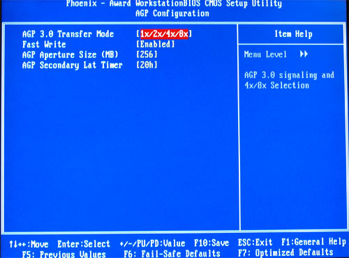
Since the ULi implementation of AGP is real AGP and not derived, the AGP adjustments will look familiar to AGP owners.

Click image to enlarge.
Reference Boards are designed for qualification and not for production. It would therefore be a mistake to dwell on the Reference Board layout, except to say that Reference Boards often influence layout of production boards. IDE, SATA, video slots and bottom edge headers all work fine where they are located. However, we hope that production boards will take a different approach to the location of the 24-pin ATX power connector. Located in about the center of the board between the CPU and rear IO ports, there is really no good way to route the heavy cable. In the center of the board, you have to be careful not to interfere with air flow or operation of the CPU and memory.
The location of the floppy connector at the bottom of the board will be a long reach for floppy users. Many buyers don't care about floppies any more, but if you still use them, the bottom of the board is an inconvenient and hard-to-reach location.
Originally published at https://www.anandtech.com/show/1733 (Wayback Machine).