
ASUS A7V600: Feature-Laden – Value-Priced
- Posted in
- Motherboards
ASUS A7V600: Board Layout
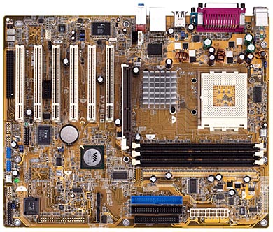
The A7V600 generally has a good layout, especially considering the price it is selling for. But as we have said in other reviews, we have yet to see the perfect board layout, and if we did, it would not likely meet the needs of some other end-users. In the end, while we can find consensus on many things related to board layout, there are others that depend on your actual case design.
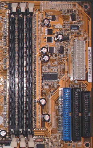
One location we are particular about is the ATX (20-pin) connector position, because the cable is very bulky and difficult to connect if poorly placed. The A7V600 ATX connector is located near the top right-hand side of the PCB to the right of the DIMM slots. This location is excellent because it keeps the bulky ATX wire bundle from obstructing the installation/uninstallation of the CPU HSF, memory modules, and any other components that you may decide to upgrade or install/uninstall after the board is mounted in the case. Since the secondary 4-pin 12V connector has appeared on recent nForce2 Ultra 400 boards, we were a little disappointed that ASUS did not include the 12V connector on the A7V600. However, a quick check of other KT600 boards found that almost all of them provide only the 20-pin ATX connector. With the fixed AGP/PCI option absent on all the KT600 boards that we have seen so far, we doubt that the extra 12V connector would make any difference in overclocking. AGP/PCI frequency will likely become a problem for KT600 boards long before we reach nForce2 overclock levels.
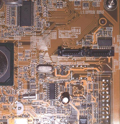
Serial ATA RAID is a feature provided by the VIA VT8237 Southbridge, and ASUS has implemented the standard two SATA connectors for regular Serial ATA, RAID 0, RAID 1, or JBOD. The connectors are placed so they are out of the way of other connectors on the board – at the middle of the board to the right. We have found that SATA connectors and cables can be quite fragile, so they are best when their location allows them to be disturbed as little as possible. ASUS places the SATA connectors well away from other connections, which should work very well.
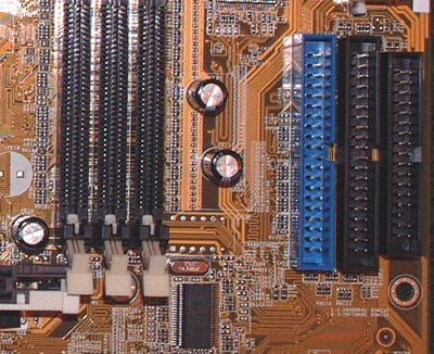
The Primary and Secondary IDE connectors are, in our opinion, best located above the midsection of the motherboard and to the right of the DIMM slots. This location allows the standard bundled IDE cables to reach the upper bays of an ATX case. This means that you will be able to install optical drives in the 1st and 2nd bays. This location also allows better air flow and case organization to be possible and allows the user to make use of the Slave connector on the bundled IDE cables. All in all, you can’t go wrong with this type of placement. Of course, this may or may not be true for your hard drives as well, but the more normal situation will be hard drives placed in bays to the right or top right of the motherboard. The above mid-right location usually works well here also, but we are much less picky about the locations of IDE RAID or SATA connections simply because the hard drives usually do not have the "reach" problem of top-bay optical drives.
The A7V600 floppy connection is also well placed with the IDE connectors in the above mid-right location. The best floppy connector location is more dependent on case design than most other connections – with some cases placing the floppy at the very top and others, at the very bottom of the external drive ‘stack’. The above midline-right location is safe for most case layouts, but you should look carefully at the case you own, or plan to buy, to be sure the floppy location will work well with your intended motherboard.
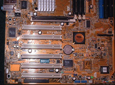
The ASUS A7V600 fortunately provides six PCI slots for expansion cards. However, like almost all 6-PCI slot designs, the three DIMM slots are crowded next to the AGP slot. This makes it difficult to impossible to add or remove a memory module without first removing the video card. We always seem to like six slots, and dislike tight DIMM slots, but you will usually have to choose one or the other with six PCI slots. Unplugging your VGA cable, then unscrewing your video card, and physically removing your video card from the AGP slot is a lot of work if you’re just trying to swap memory. You will have to decide what is more important.
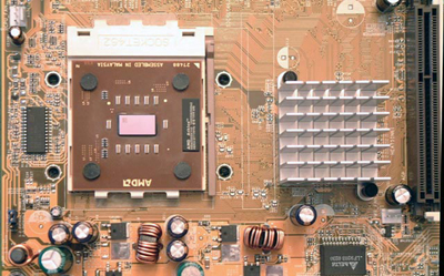
The Northbridge heatsink is the ASUS-preferred passive heatsink; we would have been surprised if ASUS used any other solution. Good arguments exist for both passive and active heatsink solutions. In the end, we can say that the large passive heatsink is effective in cooling the VIA Northbridge. The location also does not appear to interfere with any HSF solutions that you may choose for the CPU. There is plenty of room around the Socket 462.
Another pleasant surprise on the ASUS A7V600 was to see four mounting holes around the CPU socket. While this is not part of the current AMD specification, it is important to those who use water-cooling or extremely large and heavy air-cooling solutions. For most users, the four mounting holes don’t matter, but those who have invested heavily in expensive water-cooling solutions or top-line heatsinks from Swiftech, Alpha, and Thermalright will be happy to see this feature.
Originally published at https://www.anandtech.com/show/1128 (Wayback Machine).