
DFI NFII Ultra: Mean Green Dream Machine
- Posted in
- Motherboards
DFI NFII Ultra LanParty: Board Layout
The DFI NFII Ultra, like other LanParty boards, has an excellent layout. We have yet to see the perfect motherboard, however, so we do have a few minor annoyances to report.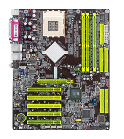
More and more top-end AMD motherboards are implementing both the standard ATX 20-pin connector and the 4-pin 12-volt connector that are part of the Pentium 4 Power Supply specification. DFI has provided both connectors on the NFII. The location of the 20-pin is virtually ideal – to the right of the DIMM slots at the top corner. This is a great location for most case designs - even full towers. Although the 4-pin 12V connector is in a common location to the left of the CPU socket we prefer the 12V to the right of the CPU socket between the CPU and DIMM slots, and as close to the top of the board as possible. The DFI worked fine with the single ATX connection, but we ran all benchmarks with both the ATX and secondary 12V connector. The DFI was built for overclocking, and the 12V connector will likely increase board stability in extreme overclocking situations.
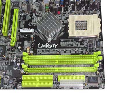
It is easy to argue both sides of DFI’s decision to use a huge passive heatsink for the nForce2 Ultra 400 Northbridge. Some will prefer the passive heatsink, while others would prefer active cooling. The proof, in the end, is how effective the solution works. We had no problems whatsoever, even overclocking as high as 228 FSB, with overheating of the heatsink. Please also take note of the cute little heatsink that DFI has applied to the power transistor, below left of the heatsink. This has been a component that often gets hot on other nForce2 boards, and we are happy to see DFI add cooling to this component. It seems to work well and stay reasonably cool.
One concern with a large passive heatsink, particularly those mounted diagonally like the nFoece2 boards, is whether large heatsinks will fit. The Thermalright SK-7, which uses a clip for connection, fit with no problem at all – even with an 80mm fan attached. However, there are no mounting holes around the CPU socket, which will be important to some. Several water-cooling blocks and a few very large heatsinks require the four mounting holes for proper setup. The mounting holes are not part of the current AMD specification, but boards targeting the enthusiast market would do well to include the mounting holes to avoid customer disappointment.
The Floppy connector and Primary/Secondary IDE connectors are in the ideal position - closer to the top of the board and to the right of the DIMM slots. This will allow IDE cables to reach the upper bays of almost any case design. Depending on your case design, you will either love or hate the IDE RAID connector locations. If you have a case with drive bays to the right of the motherboard, the location at the bottom right of the board will seem ideal. If your hard drives must mount in the upper bays of a tower case, you will probably wonder what DFI was thinking in their design. For the majority of case designs, the lower right location for hard-drive-only connections makes more sense.
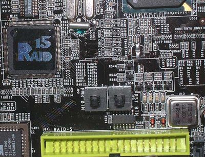
Abit received a lot of positive comments when they began putting momentary power and reset switches on their top-line overclocking boards. Everyone raved about this nice touch for the serious computer hobbyist. Well, good ideas tend to get adopted by others, and DFI has included push-button Power and Reset switches on the NFII Ultra. In fact, DFI is using the switches as part of their signature design for the LanParty boards. The onboard switches are just another touch to let the end-user know that this is a board designed for serious computer users.
Originally published at https://www.anandtech.com/show/1123 (Wayback Machine).